NEWSLETTER

Enter your email:
Construction Topics
ADS
Become a FB fan
![]()
Construction Network
![]()
 CONSTRUCTION KNOWLEDGE >>
GENERAL TECHNICAL KNOWLEDGE >>
CONSTRUCTION KNOWLEDGE >>
GENERAL TECHNICAL KNOWLEDGE >>
STRUCTURAL DESIGN
1. What are the Basics of Structural Analysis?
2. How Axial Force Crushes?
3. How Tension Force Pulls?
4. How Shear Force Tears?
5. How Bending Moments, well, Bend?
6. How Torsion Twists?
7. What are the 3 Basic Types of Connections?
8. What is a Stable and Unstable Structure?
9. What Should I Know about Expansion and Contraction?
10. What Should I Know about Creep and Fatigue?
What are the Basics of Structural Analysis?
To understand how structures work, a few basic concepts must be
explained. A structure must be designed to resist the likely forces it will encounter and
not fail or deflect too much. The common forces are snow load, wind load, earthquake load,
dead load (the actual weight of the structure itself) and live load (people or stored
materials). The building code generally sets the limits for those various design loads.
But the best place to begin an understanding of simple structural
analysis isn’t in the building codes and the stipulated loads, but in knowing how
simple structural elements work and fail.
An additional reference for understanding structural loads can be found
in the
US Department of Defense Unified Facilities Criteria (UFC) STRUCTURAL
LOAD DATA (UFC 3-310-01 - 25 May 2005).
How Axial Force Crushes?
Columns and posts are defined as vertical structural elements. A
column or post transfers load from a roof or a floor down to a foundation. For a simple
column, most of that load is an axial force that transfers downward. That axial force
(which may be caused by snow, dead and live load) will be described in pounds or kips
(thousands of pounds). It’s easy to imagine a column, say a wood 6 x 6 under a wood
outside deck, with an axial load. That load puts the column in compression. See Figure
3.1
Axial Forces.
How Tension Force Pulls?
A steel cable attached to a cable winch illustrates tension force
quite well. As the cable winch is tightened, the steel cable stretches tighter. The
tension stress in the steel cable increases (and the sag in the steel cable gets to be
less and less). At the allowable tension design stress, say 30,000 psi (depending on the
steel type) the cable will be fully loaded. If more tension force is applied with the
cable winch, at some higher stress level the steel yield strength will be reached and the
cable will snap.
![]()
How Shear Force Tears?
A beam carries load (usually horizontally) from floors and roofs to
columns. A simple beam must be designed to resist both shear and bending moments. Shear
can be illustrated by tearing open a potato chip bag. As your hands grip the bag and pull
in opposite directions, the bag starts to tear in a shear failure. To open the bag using
tension, you would grip either end of the bag and pull along a line, but in opposite
directions. It would be quite difficult to open a potato chip bag using tension, and the
chips would fly all over the floor. On the other hand, trying to open that bag using axial
force (compression) would only smash the chips.
Shear stress in a beam goes to failure along a plane, perpendicular to the beam, in which the load side of the beam displaces downward. See Figure 3.2 Shear for an illustration.
It’s important to understand that shear failures tend to happen
quickly, without much notice or warning (i.e. not much movement, creaking, deflection,
etc.). Therefore building codes tend to require a higher factor of safety against shear
failures when stipulating the allowable stresses.
![]()
How Bending Moment, well, Bend?
A simple beam that works to carry the shear stress must also be
designed for the bending moment. Think of a scaffold plank, a 2 x 10 piece of wood
spanning 6’. As you step onto the middle of the scaffold plank, you notice some
deflection downward. The scaffold plank is now experiencing a bending moment. If you think
about the actual plank directly under your feet, the wood fibers on the bottom of the
plank are in tension, they are being pulled apart as the plank bends downward. The wood
fibers on top of the scaffolding plank are in compression, they are being pushed together.
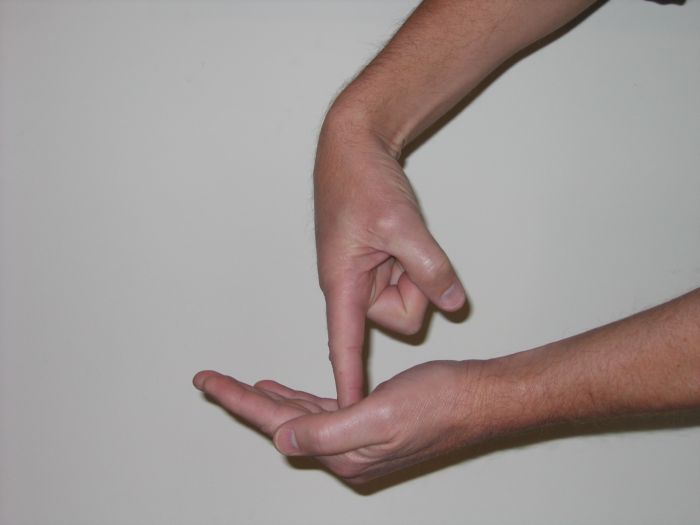
You can visualize this effect by holding your right hand outstretched, palm facing upward. Take the index finger of your left hand and poke down into the middle of your right palm. Cup your right hand just a bit. Now you get a visual of a bending moment. The skin on the bottom of your hand (around your knuckles) is in tension…the skin is being stretched tight. The skin in your palm, right near the applied load of your index finger, is in compression…the skin is bunching together. Figure 1.4 illustrates.
This concept of bending is important to understand. The scaffold plank acts as a beam, which is under load and is resisting the bending moment. Consider the cross section of the beam (i.e. the scaffold plank) at the point of load (where you are standing). When a structural element is being loaded in bending, the deflection, even if only a small amount, causes tension in the lowest fibers of the beam and compression in the top fibers. The failure due to bending moment occurs as the beam deflects and either the bottom fibers pull apart and fail in tension or the top fibers crush and fail in compression. This is illustrated in Figure 1.3 Bending Moment.
The shape of a steel “I” beam follows from this
understanding of bending moments. Since the extreme stress in tension is at the bottom of
the member and the extreme stress in compression is at the top of the member, a regular
rectangular shape would have most of its area under low stress. Only the very top and very
bottom would be under maximum stress. Figure 1.5 shows how a rectangular shape and an
“I” beam might be stressed. Obviously, since the steel rectangle beam weighs 97
lbs/foot and the W12x45 “I” beam weighs 45 lbs/foot, the steel “I”
beam is much more efficient to use.
![]()
How Torsion Twists?
Though not as common in most structural elements as axial and tension
forces, shear and bending moments, torsion should also be understood. A lintel above a
doorway acts as a good illustration for torsion. Say the lintel is a steel beam with
concrete block laid directly on top of the beam. That steel beam, then, must be designed
for shear and bending moment, but it has no torsion. All the load is coming down directly
on top of the steel beam and transferring directly down through the concrete block walls
on either side of the door.
If the steel beam has a ¼” steel plate welded onto the bottom that sticks out 6” to carry a wythe of brick off to the side, as well as the concrete block directly overhead, then that beam will see torsion. The force from the brick will try to twist that steel beam. That force is torsion and it must be considered whenever a load is applied off to one side of the center of the member.
![]()
What are the 3 Basic Types of Connections?
Beams, columns, joists and trusses all connect, both to each other
and eventually to some type of foundation. On a construction site, these structural
elements get connected in many different ways: a wood beam bolts to a steel girder, a
steel joist welds to a steel beam, a steel beam is buried into a massive concrete
foundation. To simplify structural design and analysis, though, all the many different
types of connections are grouped in three basic categories: roller, pinned and fixed.
The roller connection resists vertical forces only. Think of a steel beam sitting, on bolted, with 8 inches bearing on a 12” concrete wall. If a vertical force is applied to the steel beam, it will resist, the beam can’t move down through the wall. If a horizontal force is applied to the beam, on the other hand, the beam can easily slide further onto the wall. If the other end of the beam is lowered, the beam bearing on the concrete wall can easily pivot. Therefore, the roller connection resists vertical loads, but not horizontal loads or moments, as shown in the figure below.
The pin connection resists both vertical and horizontal forces. The pin connection shown in the figure above clearly illustrates how a beam could connect to a support. Both roller and pin connections are called simple supports, because they don’t resist moments.
Fixed supports, on the other hand, do resist moments. The figure above shows an example of a steel beam with the bearing end buried in a concrete wall. Since their can’t be any twisting or moving of the steel beam that is buried in the concrete, that connection resists any moment.
Most connections in construction are assumed to be simple supports (roller and pin connections) because the reality of getting a connection to resist a moment is challenging. A steel beam bolted to a steel column with angle clips on either side (photo) is assumed to be a pinned connection, even though a bit of moment resistance would occur. Similarly, almost any wood member nailed or bolted to another wood member is likely to be a pinned connection because of the difficulty of transferring moment through that connection.
Moment connection usually are clearly stipulated on sets of drawings and shown how to be obtained. The photo shows the welded steel plate on the top and bottom flanges of the beam to the column that transfers the moment. When connecting structural elements, you should consider if the connection can be a simple support or needs to be a fixed (moment resisting) connection.
![]()
What is a Stable & Unstable Structure?
One of the big advantages of understanding the basics of loads,
connections and structural elements is the ability to determine stable and unstable
structures. A stable structure has the proper combination of structural members, shape and
connections. A stable structure resists loads and stays in place with minimal deflection.
An unstable structure fails, not from structural members failing due to over-stress, but
from the unsoundness of the geometry and the connection types. The figure below illustrates.
Many times temporary structures are built on a job site that are unstable and dangerous. Too often the person building the temporary structure simply doesn’t understand the importance of including diagonal bracing or fixed supports to make the structure stable.
Make it a habit to look at structural systems and determine where
their stability comes from. The advanced level of understanding that will arise from
paying attention to building structures will help you to see problems before they cause
failures. Whether building a cabinet or a large building, the basics of structural design
apply.
![]()
What Should I Know about Expansion & Contraction?
In the world of construction the proper consideration of the factors of expansion and contraction is often
missed. A survey of existing buildings tends to show wall cracks near columns and cracks
in the floor. The Design Professional must detail the project to consider expansion and
contraction of materials. The best Design Professional always do, but many neglect this
important area. Since the Construction Supervisor will have to explain the cracks or bulges at the
completion of the project, he should review the drawings at the onset and feel satisfied
that the construction details will allow the building to move appropriately. One doesn’t
need an engineering degree to review these details, common sense is by far the
best guide. Incidentally, if no review is performed and building does crack or bulge, my
experience shows it is very hard to convince a group of people looking at the problem that
it is not inferior workmanship and the Contractor’s responsibility. It is always
difficult to explain the workings of expansion and contraction.
There are several forces at work in concrete causing expansion and contraction. Shrinkage occurs in concrete due to excess water in the mix. Shrinkage occurs in concrete at a decreasing rate for many years. After 90 days the average concrete shrinkage is 60% and after 1 year approximately 80% per the American Concrete Institute references. Interestingly, if the dry concrete were flooded with water, it would expand to near the original volume.
Temperature contraction tends to shorten the concrete during cold weather. It is an interesting side note that reinforced concrete only works because steel and concrete react to temperature changes in an almost identical manner. If they react differently, temperature variations would tear reinforced concrete apart. Temperature Expansion allows concrete to grow in high temperatures. These expansion and contraction forces must be considered in the concrete work.
By way of example, let’s examine a concrete slab on grade. If the concrete floor were to stay at a constant temperature its entire life, the concrete would occupy the largest volume right at the time of hydration (hardening). From that time, the concrete will continue to shrink due to to water evaporation. Therefore, in normal building, where temperature swing is minimized, concrete contraction will always be the main concern. However, if this concrete slab were part of a large driveway outside the high summer temperatures could expand the concrete to greater than its initial size and necessitate expansion joints.
Another method for dealing with contraction problems in concrete is to utilize shrinkage-compensating concrete. This special design mix both shrinks (like normal concrete) and expands to provide a concrete that has greatly reduced shrinkage. The extra cost for this concrete will typically be the Owner’s decision.
Expansion and contraction should be considered in all materials for a building project. But special attention should be paid to the concrete work. Because of its low tension strength, concrete will crack much sooner than steel or aluminum. An awareness of expansion and contraction goes a long way in avoiding potential problems.
![]()
What Should I Know about Creep & Fatigue?
Simply defined, Creep is permanent deformation (Deflection) of a
structural member under the normal working load. For example, a concrete beam will deflect
immediately under its working load, so a concrete floor slab will deflect under its own
weight and the weight of the furniture and people setting on it. Over the next 2-5 years,
though, the concrete beam will continue to creep under the same load. This addition
deflection due to creep can be three times the magnitude of the initial deflection.
If the load on the member is increased over time, the immediate structural deflection and associated creep will continue to increase. It is important for the Construction Supervisor to realize that creep is a significant happening in concrete members.
The other important concept is that of fatigue, defined as fluctuating loading which leads a structural member to fracture. Consider a concrete beam in a bridge, when a truck drives across the bridge the beam is stressed and then the load is removed. Fatigue is often considered as the material strength after 2,00,000 cycles of loading. When working on an older concrete building, it is helpful to keep the concepts of creep and fatigue in mind.
![]()