NEWSLETTER

Enter your email:
Construction Topics
ADS
Become a FB fan
![]()
Construction Network
![]()
 CONSTRUCTION KNOWLEDGE >>
ELECTRICAL >>
CONSTRUCTION KNOWLEDGE >>
ELECTRICAL >>
ELECTRICAL
1. How Can I Understand the Basics of Electricity?
2. What Are the Basic Electrical Formulas?
3. What Is the Difference between DC and AC?
4. How Is Single Phase AC Different from Three Phase AC?
5. What Is the Difference between KW and KVA?
6. What Is the Power Factor?
7. What Should I Know about Generators?
8. What Should I Know about Transformers?
9. What Should I Know about Metering, Switchgear and Panels?
10. What Do Fuses or Circuit Breakers Do?
11. What Are the Fundamentals of Electronics?
12. How Does Analog Differ from Digital?
13. How Do Fiber Optics work?
14. What Public Domain Documents are Available for Further Study?
15. Tricks of the Trade & Rules of Thumb for Electrical
Basics:
How Can I Understand the Basics of Electricity?
Imagine yourself standing with a garden hose, ready to soak some
unsuspecting passerby. The hose has water pressure and the water will
flow through the hose onto the passerby when you open the nozzle.
Prior to spraying, though, you stop and think about the similarities
between water flow in a hose and electrical current flow in a wire.
You know that a pump, operating somewhere, creates the water pressure in the hose, which is measured in pounds per square inch (psi). That water pressure places the water in a "Ready to Flow" state. Similarly, an electric generator creates an electromotive force (EMF), which is measured in volts. The electricity in the wire is in a "Ready to Flow" state and has a certain voltage or EMF.
Now if you open the nozzle of that water hose, the unsuspecting passerby will get drenched with a flow of water. That water flow gets described in gallons per minute (gpm). The electrical rate of flow is defined as Current (I) and gets measured in Amps. In order for a motor to turn or a light bulb illuminate, current must flow.
The third parallel between a water hose and an electrical wire concerns resistance. If you have several hundred feet of hose coiled at your feet that the water must pass through, not much water will emerge from the hose to spray that unsuspecting passerby. The head loss in the hose due to friction will greatly reduce the water flow and the water pressure. Similarly, resistance in an electrical circuit, either from a long wire not properly sized or an electrical device can reduce both EMF and current flow.
To recap, remember that the EMF (electromotive force measured in volts) is like the water pressure (psi), while the current flow (amps) is like the water flow (gpm).
![]()
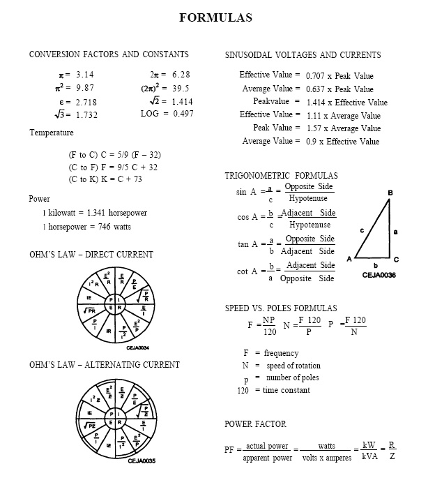
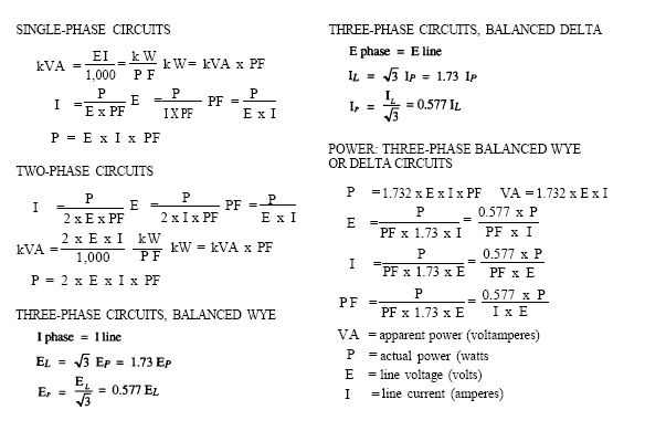
What are the Basic Electrical Formulas?
To understand electricity, the basic formulas shown below are
essential.
If you'd rather look at some electric formulas developed from the US
military. Here's another set:
![]()
What is the Difference between DC and AC?
DC stands for Direct Current. A circuit powered by a battery is a DC circuit. Most
electronic devices run on DC.
Continuing with the analogy of water in a hose, a DC circuit has all the
water flow in one direction. The reason why all electrical power isn't DC, though,
is because it can't be easily transmitted long distances or changed into
other voltages. So the early days of electrical power used DC, but
required large diameter wiring (expensive) and local power generators
(impractical).
Therefore, a more efficient type of electrical power
developed...Alternating Current. When thinking about AC, the analogy of the
water hose no longer works well. In AC, the current flow reverses
direction in a circuit, flowing first in one direction, then in the
other. This reversal of flow takes place 60 times in one second for
typical electrical AC power in America. Thus the AC power is called 60
cycle (or 60 Hertz). The normal AC power in much of the rest of the
world is 50 cycle. The number of cycles is chosen as a mostly arbitrary
standard. The map shown in this Wikipedia link
http://en.wikipedia.org/wiki/Utility_frequency illustrates the
standard voltages and frequencies most countries in the world chose.
As an aside, lights and motors tend to be designed to work at either 50 cycles or 60 cycles. The wrong frequency in lights causes a flicker and in motors more serious problems can occur. Understand that electrical appliances typically are designed for 60 cycle or 50 cycle power and will have problems with efficiency, or even safety, if the correct frequency isn't used.
AC power became the standard throughout the world, mostly because transformers allow AC power to change voltages. So Utility Companies can produce electricity and send it over high voltage lines (say 11,000 volts), then simply transform the power to 120 volts for normal use. This ability to send high voltage power over transmission lines allows more power to be sent over smaller diameter cable, and with less transmission loss, than DC power would allow.
![]()
How is Single Phase AC Different from Three Phase AC?
To begin with the simple, practical information, single phase AC power requires 3 wires: a hot, a neutral and a ground. Three phase
requires 5 wires: 3 hots, a neutral and a ground. In three phase, each
of the hot wires can complete a circuit with the neutral. Three phase
power can carry more electrical capacity than single phase. Starting a
10 hp motor (starting a motor can require 6 times more power than
running a motor) may cause a single phase line to blink or have a low
voltage. A three phase line could allow that 10 hp motor to start
without problem. Generally, three phase motors are more compact and
efficient than similarly sized single phased motors, so the use of three
phase motors is widespread. Large motors get used in so many
applications: elevators, fans, blowers, compressors, pumps, conveyor
drives, etc., so many projects require three phase electrical power.
To understand three phase power, think about the 60 cycles of alternating current electricity, discussed above. Each 1/60th of a second has a directional shift in the current. The current flows in one direction, then back in the other direction. The 3 Phase Electrical Wave figure below illustrates the black line (phase #1) flowing in one direction at 0, then flowing in the other direction at 180 and finally flowing back in the original direction at 360. The red line (phase #2) and the blue line (phase #3) start off the directional shifts at different times. This phase separation must be considered to get the correct phase rotation when wiring induction motors. In other words, one hook-up makes the motor run forward, the other hook-up makes it run backwards.
So the three phase electrical system has 3 conductors carrying voltage waveforms (shown above) that are offset in time by 120 degrees or 1/3 of a cycle.
When designing three phase electrical systems, one strives to balance the load between phases. In a 5 wire, 120/208 volt system, two of the hots create a 208 volt circuit while a hot and a neutral create a 120 volt circuit. One tries to balance the load (current), voltage and impedance on each of the phases. Of course a perfect balancing never happens. But too much of an imbalance causes higher operating temperature, shorter motor life and less efficiency.
![]()
What is the Difference between KW and KVA?
Electrical utility companies provide volt-amperes to customers, but bill
them for watts. Understanding this concept will help you better
understand many of the decisions made by project owners and electrical
engineers. Since the Power Law shown above lists Watts = Volts x Amps,
you may think that the number of volt-amperes should be the same as the
number of watts. After all, that's what the Power Law equation states.
And it's true when the load is resistive, say an electrical heating
element that uses all the power that is delivered to it by changing the
electrical energy into heat energy. A motor or a fluorescent light, on
the other hand, are reactive loads in that part of the electrical power
that goes to them gets absorbed, then returned to the circuit without
being used. The reactive portion of the load dissipates no power.
Let's look at it a different way. When trying to understand generators that are specified for a project, you will often see them listed with KVA numbers. So what does that mean? If you know that you will have 100 amps of load at 208 volts, you'd need an transformer with at least 20.8 KVA. If you installed that transformer and measured the volts you'd see 208 volts and an amp meter would show 100 amps. But since part of that current goes back into the circuit without being used, the real power (or the KiloWatts) would be less than 20.8 KW. The figure below illustrates:
So with our generator example above, if the power factor is 0.8, then the real power used will be 20.8 KVA x 0.8 power factor or 16.6 KW.
Since we're discussing generators, it's good to know that the industry standard power factor assumed for rating generators is 0.8. But the reality of what the generator will actually drive under load depends on the actual power factor. To continue with the above example, if you use a 16.6 KW generator but lots of small induction motors are being powered and the true power factor is 0.6, then the apparent power required will be 16.6 KW / 0.6 = 27.7 KVA. The right conclusion to draw, though, is to discuss and purchase generators using the KVA requirements, not the KW.
![]()
What is the Power Factor?
The illustration above shows that the power factor is a number between 0 and 1.0 that is a ratio between the true power (KW) and the apparent power (KVA). Some typical power factors are shown below:
| Various types of loads | Power factor |
| Electric resistive heating | 1.0 |
| Incandescent lighting | 1.0 |
| Incandescent lighting with a step down transformer | 0.95 to 0.98 |
| Fluorescent lighting | 0.5 to 0.95 |
| Single phase induction motor up to 1 HP | 0.55 to 0.75 |
| Single phase induction motor 1 HP to 10 HP | 0.75 to 0.85 |
| Three phase induction motor 1 HP to 10 HP | 0.75 to 0.91 |
| Electric welding transformers | 0.50 to 0.70 |
| Synchronous motors | 0.80 to 1.0 |
As you can see, power factors can vary widely depending on the loads. So why does that matter? Power companies don't like supplying the apparent power requirements but only getting paid for the true power that's used. So an industrial plant with a low power factor has to have lots more energy supplied to it than it pays for, creating an inefficiency for the power companies. As you can imagine, power companies tend to prize efficiency, so they typically bill that industrial client with the low power factor a penalty to encourage them to improve. Under-loaded induction motors often lower a power factor, so an industrial plant may replace those motors with smaller capacity motors or going with synchronous motors.
![]()
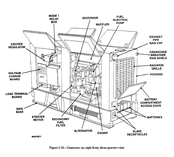
What Should I Know about Generators?
I know one thing I wish I'd known about diesel generators is that they need their oil level checked daily if they are running 24/7. I had rented a 25 KVA diesel generator for a factory we were building in the middle of nowhere. That old generator just ran and ran...till it didn't. When the service guys came out and asked me when I'd last checked the oil, I gave them that dumb blank stare. Then I responded with the pitiful, "But you never told me I needed to check the oil." Paying to help repair the engine on the generator helped me remember the lesson.
If you need to provide temporary electric on a jobsite, diesel, gasoline or propane generators often solve the problem. Trying to determine the size generator you need can also be a challenge. The following Honda website http://www.hondapowerequipment.com/genwat.asp shows the power requirements for lots of devices. The big difference in current draw for motors starting vs just running should be noted. I was also surprised how much energy computers use.
A site to compare pricing and features for industrial generators http://www.gopower.com/ shows the options available. The first decision concerns the fuel used to power the generator; the normal options are diesel, natural gas or propane. Deciding which items will be powered in a power outage determines the size of the generator, typically in KVA. The location of the proposed generator leads to the type of housing required.
As an interesting aside, I came across instructions to build the world's simplest generator. You may want to kill some time playing around with this or help a kid with a science project or some such thing. This simple device clearly shows the definition of an electric generator as a device that changes mechanical energy into electrical energy. On the other hand, a motor changes electrical energy into mechanical energy.
Volume IV of the US DOE Handbook of Electrical Science illustrates components of a generator in the figure below.
![]()
What Should I Know about Transformers?
A transformer transfers electrical energy from one circuit to another by magnetic coupling. In other words, the number of coils on the primary side of a transformer create a magnetic field when a current passes through it. Therefore, the secondary side of the circuit, with a different number of coil windings, will have a different voltage. The modern use of electricity requires that very high voltage, low current flows travel the long distances between the electrical generation source and the point of use. In almost any modern use of electricity, several voltage increases and decreases will occur. Since transformers are extremely efficient, there are few losses between their input power and output power.
The sketch below illustrates a simple transformer from Volume IV of the US DOE Handbook of Electrical Science.
![]()
![]()
What Should I Know about Metering, Switchgear and Panels?
The electrical power portion of most buildings will include metering, switchgear and distribution panels. A Construction Supervisor should have a basic understanding of what these elements do. The metering allows the power company to keep track of how much electricity gets used. The largest amount of electricity used at one time (the Demand) and the power factor also are important on buildings that have more inductive loads like motors.
Then a main breaker will be required in the switchgear, allowing the entire electrical system to be turned off. From this main breaker, the current flows through circuit breaker panels and sub-panels. Typically a one line diagram shows the general concept of the electrical power system and includes metering, switchgear and panels.
![]()
What Do Fuses or Circuit Breakers Do?
A fuse or circuit breaker protects the wiring in an electrical circuit from allowing too much current to flow. A short circuit, for example, could be caused by two wires mistakenly crossed (a nail driven through the wall and touching two wires) that could cause a huge current flow and start a fire. Without fuses and circuit breakers, electrical circuits would simply catch on fire too many times for electricity to be considered a safe and practical energy to use. Since equipment will fail and wiring problems will happen, fuses or circuit breakers need to be included in circuits for safety.
Fuses work on the simple concept that when current flows through wire it generates heat, the more current flow, the more heat. The thin wire in a fuse will only allow a certain amount of current to run through it until it heats and disintegrates. The thin wire in the fuse is now gone and no current can flow the circuit. When current was flowing through the fuse and the rest of the circuit, it was a closed circuit, but when the fuse blows, it becomes an open circuit. No current flows in an open circuit. So fuses work well, but they only work one time. After the wire in a fuse burns out, that fuse must be removed and thrown away and a new fuse must be installed.
The circuit breaker accomplishes the same function as a fuse, but uses a simple switch to detect over-current situations. Therefore the circuit breaker can trip and be reset many times. Follow the link for a slightly more detailed explanation about how circuit breakers work.
What are the Fundamentals of Electronics?
How the heck should I know? I plan and build buildings for a living. I did find some interesting US Navy training courses that provide a tremendous amount of useful information. The intro to the course follows:
NAVY ELECTRICITY AND ELECTRONICS TRAINING SERIES
The Navy Electricity and Electronics Training Series (NEETS) was
developed for use by personnel in
many electrical- and electronic-related Navy ratings. Written by, and
with the advice of, senior
technicians in these ratings, this series provides beginners with
fundamental electrical and electronic
concepts through self-study. The presentation of this series is not
oriented to any specific rating structure,
but is divided into modules containing related information organized
into traditional paths of instruction.
The series is designed to give small amounts of information that can be
easily digested before advancing
further into the more complex material. For a student just becoming
acquainted with electricity or
electronics, it is highly recommended that the modules be studied in
their suggested sequence. While
there is a listing of NEETS by module title, the following brief
descriptions give a quick overview of how
the individual modules flow together.
Module 1, Introduction to Matter, Energy, and Direct Current
introduces the course with a short history
of electricity and electronics and proceeds into the characteristics of
matter, energy, and direct current
(dc). It also describes some of the general safety precautions and
first-aid procedures that should be
common knowledge for a person working in the field of electricity.
Related safety hints are located
throughout the rest of the series, as well.
Module 2, Introduction to Alternating Current and Transformers is an
introduction to alternating current
(ac) and transformers, including basic ac theory and fundamentals of
electromagnetism, inductance,
capacitance, impedance, and transformers.
Module 3, Introduction to Circuit Protection, Control, and Measurement
encompasses circuit breakers,
fuses, and current limiters used in circuit protection, as well as the
theory and use of meters as electrical
measuring devices.
Module 4, Introduction to Electrical Conductors, Wiring Techniques, and
Schematic Reading, presents
conductor usage, insulation used as wire covering, splicing, termination
of wiring, soldering, and reading
electrical wiring diagrams.
Module 5, Introduction to Generators and Motors is an introduction
to generators and motors, and
covers the uses of ac and dc generators and motors in the conversion of
electrical and mechanical
energies.
Module 6, Introduction to Electronic Emission Tubes, and Power Supplies
ties the first five modules
together in an introduction to vacuum tubes and vacuum-tube power
supplies.
Module 7, Introduction to Solid-State Devices and Power Supplies is
similar to module 6, but it is in
reference to solid-state devices.
Module 8, Introduction to Amplifiers covers amplifiers.
Module 9, Introduction to Wave-Generation and Wave-Shaping Circuits
discusses wave generation and
wave-shaping circuits.
Module 10, Introduction to Wave Propagation, Transmission Lines, and
Antennas presents the
characteristics of wave propagation, transmission lines, and antennas.
Module 11, Microwave Principles explains microwave oscillators,
amplifiers, and waveguides.
Module 12, Modulation Principles discusses the principles of modulation.
Module 13, Introduction to Number Systems and Logic Circuits
presents the fundamental concepts of
number systems, Boolean algebra, and logic circuits, all of which
pertain to digital computers.
Module 14, Introduction to Microelectronics covers microelectronics
technology and miniature and
microminiature circuit repair.
Module 15, Principles of Synchros, Servos, and Gyros provides the
basic principles, operations,
functions, and applications of synchro, servo, and gyro mechanisms.
Module 16, Introduction to Test Equipment is an introduction to some
of the more commonly used test
equipments and their applications.
Module 17, Radio-Frequency Communications Principles presents the
fundamentals of a radiofrequency
communications system.
Module 18, Radar Principles covers the fundamentals of a radar system.
Module 19, The Technician's Handbook is a handy reference of
commonly used general information,
such as electrical and electronic formulas, color coding, and naval
supply system data.
Module 20, Master Glossary is the glossary of terms for the series.
Module 21, Test Methods and Practices describes basic test methods and practices.
Module 22, Introduction to Digital Computers is an introduction to digital computers.
Module 23, Magnetic Recording is an introduction to the use and
maintenance of magnetic recorders and
the concepts of recording on magnetic tape and disks.
Module 24, Introduction to Fiber Optics is an introduction to fiber optics.
Embedded questions are inserted throughout each module, except for
modules 19 and 20, which are
reference books. If you have any difficulty in answering any of the
questions, restudy the applicable
section.
Although an attempt has been made to use simple language, various
technical words and phrases have
necessarily been included. Specific terms are defined in Module 20,
Master Glossary.
![]()
How Does Analog Differ from Digital?
To understand analog signals, think about a microphone. The sound pressure from your voice causes an element in the microphone to vibrate. Over time that element moves with a different frequency (cycles per second) and amplitude (distance it moves or wavelength). So an analog signal is a time continuous signal that has wavelength and frequency. The stylus on a record player picks up the variations in the groove that are analogous to the actual sounds. That's where the term "Analog" comes from. The human hear also works in an analog manner, determining the in real time the vibrations that carry frequency and wavelength of the sound.
Digital signals, on the other hand, are just a series of 0s and 1s. The pattern of these 0s and 1s (called a binary system) convert an analog signal (which is the physical properties of the sounds) into bits of information that can be stored, transmitted and converted back into an analog signal. The accuracy of the conversion (the quality of the sound) depends on the sampling rate (how often the sound gets converted) and the sampling depth (how much information is included in each conversion). Think of a low quality photo from a cheap cell phone camera, the sampling rate and depth is low, so the quality of the photo is poor. Conversely, a 5 Megapixel digital camera provides an extremely clear photo.
Another key difference between digital signals and analog signals is that digital signals don't operate in real time like an analog signal. Your ear hears that sound pressure and converts it to an analog signal in real time, as the sound happens. Digital sound gets stored in bits of information and needs to be converted back to analog real time (whether in an image or a sound) to make sense to our analog selves.
A standard clock illustrates the principle in another way. As the second hand sweeps the dial and the minute and hour hands slowly move, the clocks acts as an analog device. It works continuously through time. So you can look at an analog clock and know the time is 1 minute and 37 seconds after 2:00.
A digital clock typically will show only the hours and the minutes, changing from one minute to the next. So does that make the digital clock less able to give accurate time than an analog clock? Not necessarily. Think sampling rate and sampling depth. The digital clock could be programmed to show time to the thousandth or millionth of a second. The point to remember is that neither analog nor digital signals are inherently better, just different.
The following rates for transmitting data are helpful:
| Copper phone line and dial up modem | 30 kilobits per second |
| DSO | 64 kilobits per second |
| ISDN | 144 kilobits per second |
| DSL | 1.5 megabits per second |
| T1 line (= 24 DSO lines) | 1.5 megabits per second |
| Fiber cable, commercial applications | 2 to 5 megabits per second |
| Fiber cable, top end applications | up to 30 megabits per second |
| T3 line (= 28 T1 lines) | 43 megabits per second |
![]()
How do Fiber Optics work?
With the understanding of digital signals from the section above, fiber optics become fairly easy to visualize. Think about a very long flexible piece of 2" flexible pipe, say a mile long. Imagine the inside of this pipe was completely mirrored, reflecting any light that hits the pipe wall. If you stand at one end of this pipe and shine a flashlight into the pipe, you could turn your light on and off and give Morse code signals. Your buddy at the other end of the pipe could easily see and understand the light signals coming through the pipe. That's how fiber optic cable works.
A piece of fiber optic cable is made of incredibly pure glass, so light can be transmitted miles without degradation. The thickness of the fiber optic strand is similar to a human hair. The fiber optic glass strand gets coated plastic, which allows all the light that goes in the one end to come out the other end.
So fiber optics become a great way to send digital signals. The on-off nature of digital information allows the signal to be sent at the speed of light. The light laser can turn on and off several billion times per second (try that with your flashlight!) and use light colors as well to transmit billions of bits per second through an individual fiber optic strand. At the other end of the strand, the light signal gets converted back to a digital electric signal and finally back to an analog signal.
A fiber optic line currently can carry a signal about 60 miles before it needs to be read and re-transmitted at full strength to the next transmission station.
![]()
What Public Domain Documents are Available for
Further Study?
The US Navy
Construction Electrician Basic (NAVEDTRA 14026) and the
Construction Electrician Intermediate (NAVEDTRA 14027) both provide
some excellent training for understanding electricity on the
construction site.
A complete guide to Electrical Science is provided in a 4-part manual and provides an excellent knowledge about the theory of electrical work. Volume I presents the basic theory of electricity and magnetism some basic DC circuits. It's titled DOE-HDBK-1011/1-92 (JUNE 1992) and is 166 pages. Volume II covers more DC complexity with capacitors, batteries and induction motors. It's 118 pages and titled DOE-HDBK-1011/2-92 (JUNE 1992). A solid knowledge of DC power helps AC power make more sense. Volume III addresses AC power, first in theory then in a more practical manner. It's titled DOE-HDBK-1011/3-92 (JUNE 1992) is 126 pages. Finally, Volume IV is titled DOE-HDBK-1011/4-92 (JUNE 1992) contains 142 pages and covers AC motors, transformers and test equipment.
The US Dept of Defense provides Electrical Power Supply and Distribution Manual which covers power distribution typically provided by Utility Companies. This 125 page handbook is officially called UFC 3-550-03FA (March 2005).
Another resource, more useful in design than in construction, is the US Dept of Defense Interior Electrical Systems Manual. It has 279 pages of information and is officially named UFC 3-520-01 (June 10, 2002).
The US Dept of Defense provides Design: Interior and Exterior Lighting Controls Manual which is an excellent introduction to lighting. This 125 page handbook is officially called UFC 3-530-01 (August 2006). This excellent resource shows lighting in many different types of projects and provides design and functional insight.
The US Navy Electricity and Electronics Training Series that is
listed above under What are the Fundamentals of Electronics?
does a great job at covering all basic aspects of electricity and
electronics.
![]()
Tricks of the Trade & Rules of Thumb for
Electrical Basics:
- The EMF (electromotive force measured in volts) is like the water pressure (psi), while the current flow (amps) is like the water flow (gpm).
- The power law states that Watts = Amps x Volts, but always consider the power factor.
- The power factor is the real power (in kilowatts) divided by the apparent power (in kilovolts x amps) and is always between 0 and 1.
- Analog signals are continuous in time and have frequency and wavelength, digital signals are bits that get stored.
- Understand fiber optics by thinking about a long flexible pipe
with a flashlight shining into one end giving Morse code.
![]()